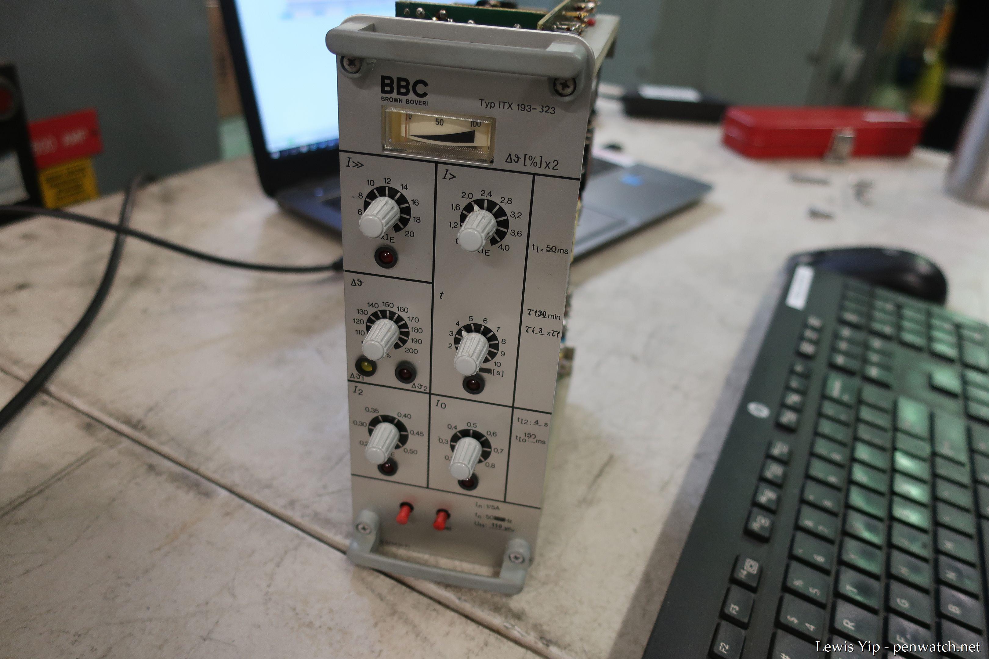
A static protection relay: the BBC ITX 193
Posted: , Updated: Category: engineering Category: electrical-engineeringThe Network protection and automation guide (NPAG) states there are four generations of protection relay technologies:
- Electromechanical - has moving parts.
- Static - moving parts replaced by analogue electronics.
- Digital - analogue electronics replaced by microprocessors.
- Numerical - microprocessors made more powerful - many more functions added.
My career has mostly been on a site where the standard overcurrent relays changed from electromechanical (e.g. GEC CAG induction disc relays) straight to digital relays (e.g. Areva MCGG microprocessor based relays.)
I did get to look at an example of a complex static relay - the BBC ITX 193 motor protection relay.
BBC, or Brown Boveri Corporation, was a predecessor of ABB, a modern mega-corporation mainly dealing in electrical products.
We pulled one of these relays for statutory maintenance in 2020 and I took the opportunity to take some photos.
Engineering information
The relay implements a full suite of motor protection functions, including -
- Overload
- Short circuit
- Starting time / blocked rotor
- Unbalanced load
- Earth fault
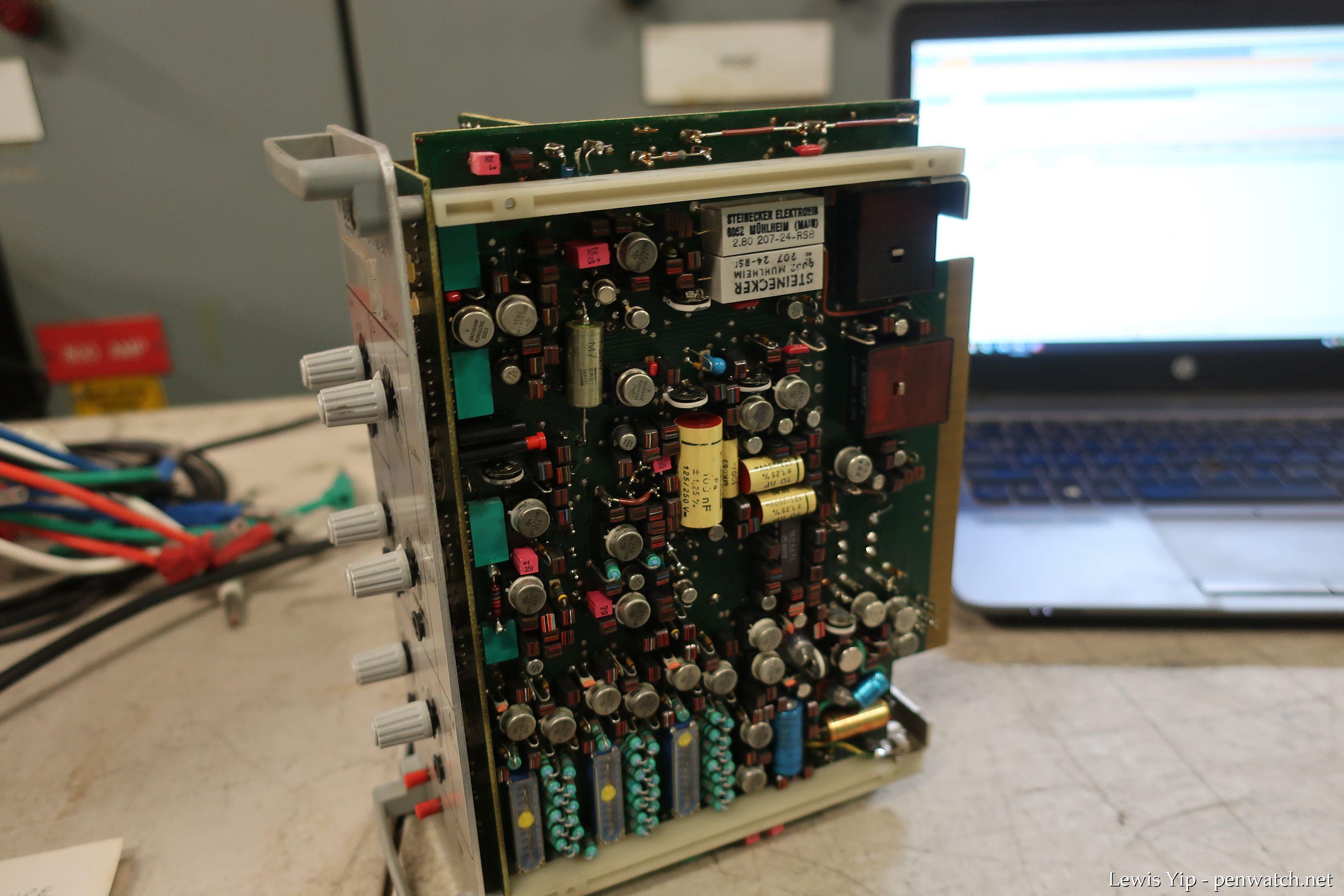
Because the relay is electronic, all these functions are implemented in a fraction of the space that would have been needed for an electromechanical relay. The modern trend is to pack more functions into relays, even increasing their physical size, not really to make the relays any smaller.
Interestingly there appear to be a number of relay characteristic values (time constants, etc.) stamped on the relay’s face plate. A quick reading of the manual doesn’t say whether these are field adjustable or not. I suspect these values were specified when the relay was ordered, and aren’t field adjustable.
I have uploaded scanned copies of the application guide and the instruction manual for the BBC ITX 193, which may be of interest (or even practical use) to some readers.
Sneaky switches of an unusual type
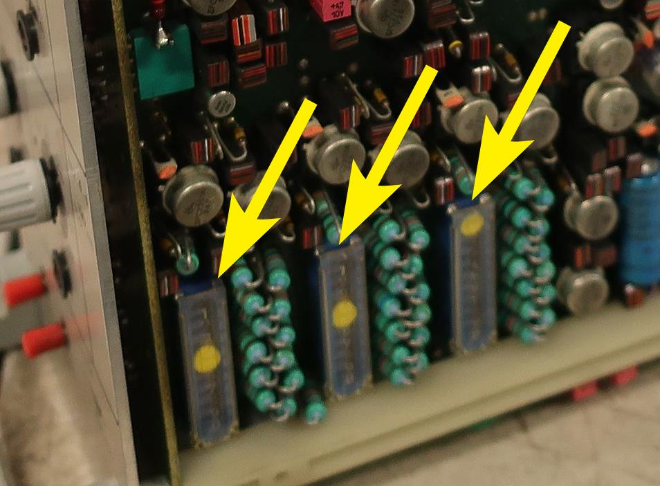
My main memory of these relays is the sneaky settings switches that are located on the circuit board. These switches aren’t visible from the front when the relay is installed! It took us a while to find these switches.
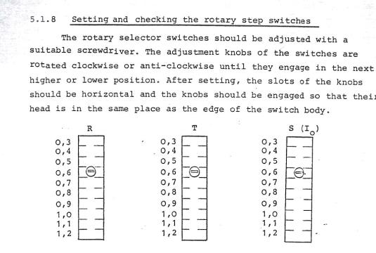
The switches are a “rotary step switches”, an interesting type of multi-position slide switch I had never seen before, and have never seen since.
You move the slider between positions using a screwdriver to turn a little geared wheel.
This is a very secure way of setting the switch position, but these switches appear to have been an evolutionary dead end. I looked in the RS Components catalog and couldn’t find anything like them.
I believe the function of these switches is to make fine adjustments to the three current measurement units “R, S, and T” in the relay (two phase elements and one earth-fault element.)
User modification… expected?
These relays belong to a bygone era of electronics where field modifications were both expected and allowed for. The instruction manual states —
5.1.9 Modifying the relay on site
A number of changes to the function of the relay, achieved by correspondingly positioning soldered links in relation to the application, have been described in the previous sections. Particular care should be taken when soldering should be position of a soldered link need to be changed. In some cases recalibration is also necessary.
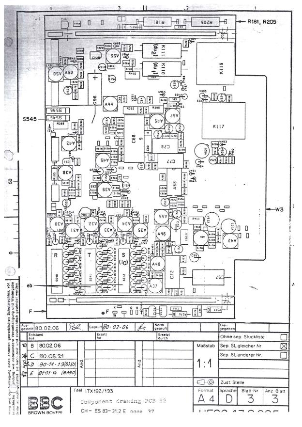
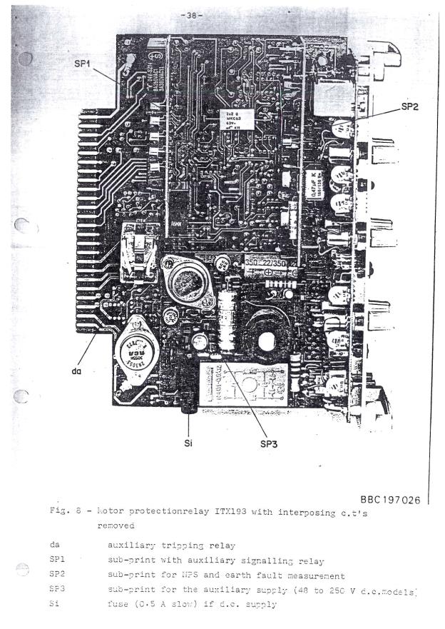
Also gone are the days where manufacturers used to include technical drawings of the product in the instruction manual.
Conclusion
Protection relays are weird and wonderful devices, especially the old ones. :)